2017年12月14日 星期四

Installing a FortiGate in NAT/Route mode(以NAT或Router模式安裝FortiGate)


In this example, you will learn how to connect and configure a new FortiGate unit in NAT/Route mode to securely connect a private network to the Internet.
在此範例中,你可以學習到如何將FortiGate單元調整為NAT或是Route模式,並將之安裝到內網與網際網路的連接點上。
In NAT/Route mode, a FortiGate unit is installed as a gateway or router between two networks. In most cases, it is used between a private network and the Internet. This allows the FortiGate to hide the IP addresses of the private network using network address translation (NAT).*
FortiGate單元在NAT模式下,其作用類似連接內外網的Gateway;在Route模式下,其作用類似連接內外網的Router,在大多數情況下,FortiGate會安裝在內部網路與網際網路之間,這樣才能使用NAT模式隱藏內網使用的private IP,使其連接內部與外部網路。
(註:開始安裝前需要先決定FortiGate實體port使用的模式是Switch還是Interface,這部分請參考 Choosing your FortiGate's switch mode)


1. Connecting the network devices and logging onto the FortiGate

連接網路設備並登入FortiGate
Connect the FortiGate’s Internet-facing interface(typically WAN1) to your ISP-supplied equipment and Connect a PC to the FortiGate using an internal port (typically port 1).
將FortiGate連接到網際網路方面的介面(通常為WAN1)連接到ISP業者提供的設備上(通常是接到中華電信的小烏龜上),並將一台電腦的網路線連接到FortiGate連接內網方面的Port(通常為port 1)
Power on the ISP’s equipment, the FortiGate unit, and the PC on the internal network.

確保ISP業者的設備、FortiGate以及連接在網路上的電腦這三者的電源皆已啟動

From the PC on the internal network, connect to the FortiGate’s web-based manager using either FortiExplorer or an Internet browser (for information about connecting to the web-based manager, please see your models QuickStart Guide).

從連上此網路的電腦上進行操作,使用FortiExplorer或是網頁瀏覽器,連到FortiGate的網頁管理介面,網頁管理介面的IP請參考各型號產品的QuickStart Guide
(網頁管理介面的預設IP為192.168.1.99/24)
Login using an admin account (the default admin account has the username admin and no password).

使用帳號admin登入 (預設帳號admin,無密碼)

2. Configuring the FortiGate’s interfaces

設定FortiGate的介面


Go to System > Network > Interfaces and edit the Internet-facing interface.

點選到 系統 > 網路 > 介面 ,並在用於連接網際網路的介面項目點擊編輯
If your FortiGate is directly connecting to your ISP, set Addressing Mode to Manual and set the IP/Netmask to the public IP address your ISP has provided you with.

若您的FortiGate是直接連接到ISP的話,請在該介面上設定ISP業者提供的IP及遮罩。(具體方法為點選到wan1 > 編輯 > 在Addressing mode點選到Manual,再輸入IP及遮罩)
If have some ISP equipment between your FortiGate and the Internet (for example, a router), then the wan1 IP will also use a private IP assigned by the ISP equipment. If this equipment uses DHCP, set Addressing Modeto DHCP to get an IP assigned to the interface.


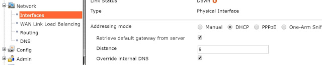
若是在FortiGate及網際網路之間裝有ISP業者提供的其他設備,則FortiGate在wan1使用的IP同樣會是Private IP以對應ISP業者的設備(小烏龜),如果該設備(小烏龜)有啟用DHCP功能,則設定FortiGate的wan1介面時,請選擇DHCP模式直接由該設備(小烏龜)自動派發IP及遮罩

If the ISP equipment does not use DHCP, your ISP can provide you with the correct private IP to use for the interface.
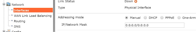
若ISP業者提供的設備(小烏龜)沒有DHCP功能,則可以向ISP業者詢問正確對應的Private IP以便設定FortiGate的wan1介面

Edit the internal interface (called lan on some FortiGate models).
編輯internal介面(部分型號上,此項目為lan)
Set Addressing Mode to Manual and set the IP/Netmask to the private IP address you wish to use for the FortiGate.
在FortiGate上,對該介面設定IP/遮罩


3. Adding a default route

設定預設路由
Go to Router > Static > Static Routes (or System > Network > Routing, depending on your FortiGate model) and create a new route.
點擊 路由(Router) > 靜態(Static) > 靜態路由(Static Routes)
或是 系統(System) > 網路(Network) > 路由(Routing)
[依型號不同而有些微差異]進入後,點擊create  new開始設定預設路由

Set the Destination IP/Mask to 0.0.0.0/0.0.0.0, the Device to the Internet-facing interface, and the Gateway to the gateway (or default route) provided by your ISP or to the next hop router, depending on your network requirements.

設定目的IP/遮罩這個項目為 0.0.0.0/0.0.0.0,設備選擇連接到外部網路的FortiGate介面(通常為wan1),Gateway設定由ISP業者提供或是在ISP業者的設備與FortiGate之間有Router或其他具路由功能的設備的話,就設定成與該設備連接的該設備端口IP,此項目依您的網路架構而定。

4. (Optional) Setting the FortiGate’s DNS servers


The FortiGate unit’s DNS Settings are set to use FortiGuard DNS servers by default, which is sufficient for most networks. However, if you need to change the DNS servers, go to System > Network > DNSand add Primary and Secondary DNS servers.

FortiGate產品的預設DNS設定為FortiGuard DNS伺服器,對於大部分的網路環境來說,此設定已經足以滿足大多數的環境需求,如果你需要變更DNS相關設定,請照以下步驟點選:
系統(System) > 網路(Network) > DNS ,點擊specify,並在 Primary 以及 Secondary DNS輸入所需的DNS設定


5. Creating a policy to allow traffic from the internal network to the Internet*

建立政策使流量從內網移動到外網

Go to Policy & Objects > Policy > IPv4 and create a new policy (if your network uses IPv6 addresses, go to Policy & Objects > Policy > IPv6).
點選到政策&物件 > 政策 > IPv4 > create new 建立新的過濾規則
(若要使用IPv6的話,先啟用IPv6:System > Config > Features > IPv6 > Apply,接著再建立過濾規則:Policy & Objects > Policy > IPv6 > )

Set the Incoming Interface to the internal interface and the Outgoing Interface to the Internet-facing interface.
將來源介面(Incoming Interface)設為內網使用的介面(internal),將目的介面(Outgoing Interface)設為連接網際網路部分的介面(wan1)
Make sure the Action is set to ACCEPT. Turn on NAT and make sure Use Destination Interface Address is selected (later versions of FortiOS 5.2 call this option Use Outgoing Interface Address).
確定動作(Action)設定為接受(ACCEPT)。啟用NAT(預設已啟用)並確定有勾選"使用出口端介面位址"(預設已勾選)(FortiOS 5.2.x的版本中,此項目為使用出去介面位址。)
Scroll down to view the Logging Options. In order to view the results later, enable Log Allowed Traffic and select All Sessions.

將畫面向下拖動到Logging Options的部分,為了稍後可以確認到紀錄(log),啟用Log Allowed Traffic並點選到All Sessions


5. Results

You can now browse the Internet using any computer that connects to the FortiGate’s internal interface.
您現在可以透過任意一台與FortiGate內網連接的電腦隨意瀏覽網頁
You can view information about the traffic being processed by your FortiGate by going to System > FortiView > All Sessions and finding traffic that has the internal interface as the Src Interface and the Internet-facing interface as the Dst Interface.

(圖片為使用FortiGate進行前述設定後,電腦透過FortiGate瀏覽網頁留下的紀錄)

您可以照以下步驟操作來檢視那些通過FortiGate留下的資訊:
點擊到 System > FortiView > All Sessions,要找到您瀏覽網頁的紀錄,請分別確認來源(Src Interface)為內網(internal)以及目的(Dst Interface)為連接網際網路的介面(通常為Wan1)


If these two columns are not shown, right-click on the title row, select Src Interface and Dst Interface from the dropdown menu, and then select Apply.

若這兩列並未出現,在標題行上點擊滑鼠右鍵,在下拉式選單中選擇來源介面(Src Interface)目的介面(Dst Interface),並點擊確認(Apply)
(系統版本不同,則部分介面也會有不同的外觀或位在不同的地方)

2017年12月5日 星期二

Choosing your FortiGate's switch mode(選擇FortiGate的運作模式)

This section contains information to help you determine which internal switch mode your FortiGate should use, a decision that should be made before the FortiGate is installed

這個部分包含的資訊可幫助您決定FortiGate應該選擇何種運作模式,此選擇應該在FortiGate進行安裝前提前決定


What is the internal switch mode?

internal switch模式是啥?(實體Port在運行時的模式,但由於意義不大,這名子之後的版本就被拿掉了,要進入CLI才能看得到這個名稱)

The internal switch mode determines how the FortiGate’s physical ports are managed by the FortiGate. The two main modes are Switch mode and Interface mode.
internal switch模式可判斷實體port是如何被FortiGate管理的,internal switch模式包含兩個項目,一項為Switch 模式,另一項為Interface模式。

What are Switch mode and Interface mode and why are they used?

Switch 模式跟Interface模式又是甚麼?幹嘛要用它們?


In Switch mode, all the internal interfaces are part of the same subnet and treated as a single interface, called either lan or internal by default, depending on the FortiGate model. Switch mode is used when the network layout is basic, with most users being on the same subnet.
Switch 模式:
所有內部介面皆屬於同一個子網段,所有Port皆視作單一介面,這個單一介面在預設情況下也可稱做lan或是internal,端看FortiGate模式怎麼設定,Switch模式為出場時的預設項目,基本上大多數無特殊要求的使用者皆使用此項設定

(顧名思義,Switch模式就跟Switch的特性相似,稍微接觸過Switch的人可以知道,Switch無法在單一Port上設定IP,這裡也一樣,在Switch模式下只能將IP設定在整個介面上,若要設定各個單一Port做不同用途,就需要改成另一個模式了)

In Interface mode, the physical interfaces of the FortiGate unit are handled individually, with each interface having its own IP address. Interfaces can also be combined by configuring them as part of either hardware or software switches, which allow multiple interfaces to be treated as a single interface. This mode is ideal for complex networks that use different subnets to compartmentalize the network traffic.
Interface模式:
FortiGate的所有Port將分別被視作單一介面,所有Port皆可擁有自己的IP位址,各個Portu也可藉著設定硬體或軟體方式組合成同一個介面,此法可達成多個擁有複數Port的介面同時存在,此模式適用於同時存在多個子網路的複雜網路

Which mode is your FortiGate in by default?

你的FortiGate預設模式為何?


The default mode that a FortiGate starts in varies depending on the model. To determine which mode your FortiGate unit is in, go to System > Network > Interfaces. Locate the lan or internal interface. If the interface is listed as a Physical Interface in the Type column, then your FortiGate is in Switch mode. If the interface is a Hardware Switch, then your FortiGate is in Interface mode.

FortiGate的預設模式取決於型號,若要確認您手上的FortiGate產品目前的模式,先登入WEB管理介面,點選到系統(System) > 網路(Network) > 介面(Interfaces),點選到畫面中的Internal(也可能為lan),確認"類型(Type)的資訊,若此處顯示為Physical Interface,則您持有的FortiGate產品目前即為Switch模式,若此處顯示為Hardware Switch,則您持有的FortiGate產品目前即為Interface模式。

此處的判斷方式事實上並不一定正確,原因是5.2的版本從最初的5.2.0開發到現在的5.2.12,後面的版本,有時候會做出一些顯示上的修改,有時會參照其他的版本來增加或修改模組,如5.4或5.6的版本。
另一個相對的判斷方法則是看介面下的項目數量或名稱,60C本身有8個port,共為2個WAN,1個DMZ以及5個internal port,在預設情況下,剛登入網頁管理介面時,在介面(Interfaces)看到的項目會有4個,分別為wan1、wan2、dmz以及internal,在switch模式下,internal的5個port全部都包含在internal介面中,在Interface模式下,則會看到5個internal port出現在介面中,名稱分別是internal 1到internal 5。
Switch 模式

Interface 模式

How do you change the mode?

你該如何切換這兩個模式

If you need to change the mode your FortiGate unit is in, first make sure none of the physical ports that make up the lan or internal interface are referenced in the FortiGate configuration (for example, in a policy or DHCP server). If you FortiGate model has a Switch Controller, you may need to disable it before you can change the internal switch mode.
若你需要在所持有的FortiGate產品上切換模式,首先要先確定在介面(Interfaces)的internal(舊版為lan)底下的所有引用(referenced)皆為0,也就是刪除所有設定,比如政策(policy)或是DHCP等設定。
確認Ref引用數為0

在internal點又鍵選取Change Mode
點選到Interface Mode


待機器重開完,重新登入網頁管理介面即可看到介面已經變更

Go to System > Dashboard > Status and enter either of the following commands into the CLI Console:
另一個切換方法則是透過CLI 修改,若手上有Console線,可直接接上FortiGate設備進行操作,若無,亦可用預設程式操作:登入網頁管理介面 > 系統管理(System) > 儀錶板(Dashbord) > 狀態(Statue) > 命令列控制台(CLI Console)
  1. Command to change the FortiGate to switch mode:切換到Switch模式的指令:
    config system global
         set internal-switch-mode switch
    End
  2. Command to change the FortiGate to interface mode:切換到Interface模式的指令:
    config system global
         set internal-switch-mode interface
    End

2017年6月16日 星期五

使用FTP Server備份Router的IOS或設定

首先設定本機的IP,設完接著設定FTP程式,本LAB使用3C Daemon程式(此程式同時具有TFTP及FTP的功能),啟動程式後,先點選到FTP Server欄位,再點選到Configure FTP Server,設定FTP存取資料用的資料夾路徑,同時,設定帳號及密碼,帳密在稍後需要使用到
(此處的FTP帳密,在LAB中設為admin及123456)

登入Router進行設定:
Router#configure terminal
Enter configuration commands, one per line.  End with CNTL/Z.

設定Router上的FTP程式使用的預設帳號密碼:

Router(config)#ip ftp username admin
Router(config)#ip ftp password 12345
Router(config)#end
Router#

將IOS備份到FTP伺服器(資料夾)

Router#copy flash:c1841-adventerprisek9-mz.150-1.M10.bin ftp:
Address or name of remote host []? 192.168.10.1                           輸入FTP伺服器的IP
Destination filename [c1841-adventerprisek9-mz.150-1.M10.bin]?
Writing c1841-adventerprisek9-mz.150-1.M10.bin !!!!!!!!!!!!!!!!!!!!!!!!!!!!!!!!!!!!!!!!!!!!!!!!!!!!!!!!!!!!!!!!!!!!!!!!!!!!!!!!!!!!!!!!!!!!!!!!!!!!!!!!!!!!!!!!!!!!!!!!!!!!!!!!!!!!!!!!!!!!!!!!!!!!!!!!!!!!!!!!!!!!!!!!!
43126032 bytes copied in 52.940 secs (814621 bytes/sec)

備份結束後,前往FTP資料夾檢視,確認檔案是否存在

設定檔的備份指令如下:

Router#copy startup-config ftp:

待指令執行完畢,同樣前往FTP資料夾確認檔案存在與否

使用TFTP Server備份Router的IOS或設定

本LAB中使用的是3C-daemon這個程式,在啟動程式前,先設定好本機的IP,便可在啟動時,自動將該IP設為TFTP伺服器的IP。(此處LAB,本機IP設定為192.168.10.1/24)

接著,設定TFTP伺服器存取資料的資料夾:
先點擊左側的Configure TFTP Server圖示

設定存取資料的資料夾


設定完成後,就可以開始做備份還原的動作了


一.Router備份IOS:

1.先將Console線以及網路線都接到Router上,Port隨意
2.登入Router後,先檢視IOS的名稱,一會需要用到

Router>
Router>enable
Router#show version 
Cisco IOS Software, 1841 Software (C1841-ADVENTERPRISEK9-M), Version 15.0(1)M10, RELEASE SOFTWARE (fc1)
Technical Support: http://www.cisco.com/techsupport
Copyright (c) 1986-2013 by Cisco Systems, Inc.
Compiled Tue 26-Feb-13 12:28 by prod_rel_team

ROM: System Bootstrap, Version 12.4(13r)T, RELEASE SOFTWARE (fc1)

Router uptime is 22 minutes
System returned to ROM by power-on
System image file is "flash:c1841-adventerprisek9-mz.150-1.M10.bin"          <-------------------
Last reload type: Normal Reload

 --More-- 

3.設定Router的IP,在接上網路線的Port上設定IP:

Router#
Router#configure terminal 
Router(config)#
Router(config)#interface fastEthernet 0/0                 (接哪個Port就到哪邊設定)
Router(config-if)#
Router(config-if)#ip address 192.168.10.2 255.255.255.0
Router(config-if)#no shutdown 
Router(config-if)#end
Router#

4.測試IP設定是否有誤:
從Router上Ping TFTP server,確認IP是否互通,不通就要回頭查看哪邊出錯

成功Ping通應如下列訊息
Router#ping 192.168.10.1

Type escape sequence to abort.
Sending 5, 100-byte ICMP Echos to 192.168.10.1, timeout is 2 seconds:
.!!!!
Success rate is 80 percent (4/5), round-trip min/avg/max = 1/1/1 ms
Router#

5.開始將Router中的IOS備份到TFTP中

Router#
Router#copy  flash:c1841-adventerprisek9-mz.150-1.M10.bin  tftp   IOS名稱請參照先前的資訊
Address or name of remote host []? 192.168.10.1                               輸入TFTP伺服器的IP
Destination filename [c1841-adventerprisek9-mz.150-1.M10.bin]?    設定備份起來的檔案名稱
!!!!!!!!!!!!!!!!!!!!!!!!!!!!!!!!!!!!!!!!!!!!!!!!!!!!!!!!!!!!!!!!!!!!!!!!!!!!!!!!!!!!!!!!!!!!!!!!!!!!!!!!!!!!!!!!!!!!!!!!!!!!!!!!!!!!!!!!!!!!!
43126032 bytes copied in 59.860 secs (720448 bytes/sec)
Router#

複製成功,接著到本機的TFTP資料夾中,確認檔案存在就表示備份成功

PS:若是IOS檔案的大小超過16MB的話,檔案傳到一半,你可能會看到類似下列的訊息

!!!!!!!!.....
%Error writing tftp://192.168.10.1/c1841-adventerprisek9-mz.150-1.M10.bin (Timed out).....

原因是設備的TFTP的傳輸容量限制為16MB,超過就會出錯,這時,需要換成其他方式來傳輸,可以改用rcp或是ftp。


備份設定黨的方法相似,指令如下:
Router#
Router#copy  startup-config  tftp:   IOS名稱請參照先前的資訊
Address or name of remote host []? 192.168.10.1                               輸入TFTP伺服器的IP
Destination filename [Router-confg]?                 設定備份起來的檔案名稱,括號內為預設名稱
Writing startup-config...!!
[OK - 621 bytes]

621 bytes copied in 0.002 secs (310500 bytes/sec)

Router#

複製成功,接著到本機的TFTP資料夾中,確認檔案存在就表示備份成功

PS:若設定檔的大小超過16MB的話,同樣可能會出現Error writing的錯誤訊息

2017年5月31日 星期三

網路線的小知識

網路線為4條雙絞線組成,而雙絞線依線路與外部層之間是否有進階的訊號阻隔層而分成兩種

1.無遮蔽式雙絞線


2.遮蔽式雙絞線


市面上常見的網路線,通常皆為無遮蔽式雙絞線。

雙絞線實際上是由8條銅線組成,每條銅線在外部包覆不同顏色的塑膠外皮區分,


網路線的接頭有兩種接法:

TIA/EIA-568A:白綠、綠、白橙、藍、白藍、橙、白棕、棕
TIA/EIA-568B:白橙、橙、白綠、藍、白藍、綠、白棕、棕

不同的接法用於區分線路屬於直線網路線還是跳線網路線
(一些設備的連接需要使用到跳線網路線)


直線網路線(Straight-through):
兩端接口同樣為TIA/EIA-568A或是TIA/EIA-568B

跳線網路線(Crossover):
一端接口為TIA/EIA-568A,另一端接口則是TIA/EIA-568B

Switch忘記密碼的補救方法

Lab環境:Cisco 2960實機

模擬Switch已有設定資料時,忘記登入帳密應如何重設
註:此方法需要將設備重新開機,請自行斟酌現場設備是否可以重開

[模擬環境建置]

接線進入2960增加設定,當作原有設定資料:

Switch>
Switch>enable 
Switch#configure terminal
Enter configuration commands, one per line.  End with CNTL/Z.
Switch(config)#
Switch(config)#vlan 100
Switch(config-vlan)#
Switch(config-vlan)#no shutdown 
%VLAN 100 is not shutdown.
Switch#
*Mar  1 01:37:20.484: %SYS-5-CONFIG_I: Configured from console by consolehow

設定完畢,以啟用Vlan 100當作舊有設定,設完檢視一下是否設定成功:

Switch(config-vlan)#exit
Switch(config)#
Switch#do show vlan brief 

VLAN Name                             Status    Ports
---- -------------------------------- --------- -------------------------------
1    default                          active    Fa0/1, Fa0/2, Fa0/3, Fa0/4
                                                Fa0/5, Fa0/6, Fa0/7, Fa0/8
                                                Fa0/9, Fa0/10, Fa0/11, Fa0/12
                                                Fa0/13, Fa0/14, Fa0/15, Fa0/16
                                                Fa0/17, Fa0/18, Fa0/19, Fa0/20
                                                Fa0/21, Fa0/22, Fa0/23, Fa0/24
                                                Gi0/1, Gi0/2
100  VLAN0100                         active  
1002 fddi-default                     act/unsup
1003 token-ring-default               act/unsup
1004 fddinet-default                  act/unsup
1005 trnet-default                    act/unsup
Switch#

接著,設定舊有密碼:


Switch#configure terminal 
Enter configuration commands, one per line.  End with CNTL/Z.
Switch(config)#
Switch(config)#enable secret abcde

存檔

Switch(config)#
Switch(config)#do copy running-config startup-config
Destination filename [startup-config]?
Building configuration...
[OK]

Switch#

至此,LAB環境準備完畢

[密碼重置操作]

LAB目標:在確保原有設定的情況下,更改密碼

LAB環境至此建置完畢

此處需要將機器重開機,所以,拔掉電源線,按住面板按鈕後,插回電源線

順利的話,會見到如下畫面:


Boot Sector Filesystem (bs) installed, fsid: 2
Base ethernet MAC Address: 00:1b:0c:6d:78:80
Xmodem file system is available.
The password-recovery mechanism is enabled.

The system has been interrupted prior to initializing the
flash filesystem.  The following commands will initialize
the flash filesystem, and finish loading the operating
system software:

    flash_init
    boot


switch:

輸入flash_init:

switch:
switch: flash_init
Initializing Flash...
flashfs[0]: 5 files, 1 directories
flashfs[0]: 0 orphaned files, 0 orphaned directories
flashfs[0]: Total bytes: 32514048
flashfs[0]: Bytes used: 9835008
flashfs[0]: Bytes available: 22679040
flashfs[0]: flashfs fsck took 9 seconds.
...done Initializing Flash.

switch:


此時先檢視一下設定檔是否存在:

switch: dir flash:
Directory of flash:/

    3  -rwx  616       <date>               vlan.dat
    4  -rwx  1912      <date>               private-config.text
    5  -rwx  3096      <date>               multiple-fs
  620  -rwx  9824980   <date>               c2960-lanbasek9-mz.122-55.SE10.bin
    6  -rwx  1690      <date>               config.text

22679040 bytes available (9835008 bytes used)

switch:

設定檔為config.text,修改此項目,使設定暫時不被讀取:

switch:rename flash:config.text flash:config.old

輸入完,再次檢視設定檔,確認修改成功:

switch: dir flash:
Directory of flash:/

    3  -rwx  616       <date>               vlan.dat
    4  -rwx  1912      <date>               private-config.text
    5  -rwx  3096      <date>               multiple-fs
  620  -rwx  9824980   <date>               c2960-lanbasek9-mz.122-55.SE10.bin
    6  -rwx  1690      <date>               config.old

22679040 bytes available (9835008 bytes used)

switch:

輸入boot啟動:

switch: boot
Loading "flash:/c2960-lanbasek9-mz.122-55.SE10.bin"...@@@@@@@@@@@@@@@@@@@@@@@@@@@@@@@@@@@@@@@@@@@@@@@@@@@@@@@@@@@@@@@@@@@@@@@@@@@@@@@@@@@@@@@@@@@@@@@@@@@@@@@@@@@@@@@@@@@@@@@@@@@@@@@@@@@@@@@@@@@@@

                (中間資訊省略)

Cisco IOS Software, C2960 Software (C2960-LANBASEK9-M), Version 12.2(55)SE10, RELEASE SOFTWARE (fc2)
Technical Support: http://www.cisco.com/techsupport
Copyright (c) 1986-2015 by Cisco Systems, Inc.
Compiled Wed 11-Feb-15 11:46 by prod_rel_team


Press RETURN to get started!


按下Enter後,會出現警告訊息以及自動設定精靈的詢問,輸入NO:

         --- System Configuration Dialog ---

Enable secret warning
----------------------------------
In order to access the device manager, an enable secret is required
If you enter the initial configuration dialog, you will be prompted for the enable secret
If you choose not to enter the intial configuration dialog, or if you exit setup without setting the enable secret,
please set an enable secret using the following CLI in configuration mode-
enable secret 0 <cleartext password>
----------------------------------
Would you like to enter the initial configuration dialog? [yes/no]: no
Switch>

此時登入已不需要密碼:

Switch>
Switch>enable
Switch#

將設定檔改回原名,使其可以被辨識:

Switch#rename flash:config.old flash:config.text
Destination filename [config.text]?
Switch#

確認名稱已經改回去:

Switch#
Switch#show flash:

Directory of flash:/

    2  -rwx        1048   Mar 1 1993 00:00:59 +00:00  multiple-fs
    3  -rwx         616   Mar 1 1993 01:36:12 +00:00  vlan.dat
  620  -rwx     9824980   Mar 1 1993 00:03:22 +00:00  c2960-lanbasek9-mz.122-55.SE10.bin
    6  -rwx        1690   Mar 1 1993 00:02:05 +00:00  config.text

32514048 bytes total (22683136 bytes free)
Switch#

讀取原有設定檔:

Switch#
Switch#copy flash:config.text system:running-config 
Destination filename [running-config]?
% Generating 1024 bit RSA keys, keys will be non-exportable...
*Mar  1 00:28:46.484: %LINEPROTO-5-UPDOWN: Line protocol on Interface Vlan100, changed state to down
*Mar  1 00:28:46.954: %LINEPROTO-5-UPDOWN: Line protocol on Interface Loopback0, changed state to up[OK]

*Mar  1 00:28:48.439: %LINK-5-CHANGED: Interface Vlan1, changed state to administratively down
*Mar  1 00:28:49.470: %SSH-5-ENABLED: SSH 1.99 has been enabled
% Login disabled on line 1, until 'password' is set
% Login disabled on line 2, until 'password' is set
% Login disabled on line 3, until 'password' is set
% Login disabled on line 4, until 'password' is set
% Login disabled on line 5, until 'password' is set
% Login disabled on line 6, until 'password' is set
% Login disabled on line 7, until 'password' is set
% Login disabled on line 8, until 'password' is set
% Login disabled on line 9, until 'password' is set
% Login disabled on line 10, until 'password' is set
% Login disabled on line 11, until 'password' is set
% Login disabled on line 12, until 'password' is set
% Login disabled on line 13, until 'password' is set
% Login disabled on line 14, until 'password' is set
% Login disabled on line 15, until 'password' is set
% Login disabled on line 16, until 'password' is set
1690 bytes copied in 12.071 secs (140 bytes/sec)
Switch#
*Mar  1 00:28:57.180: %PKI-4-NOAUTOSAVE: Configuration was modified.  Issue "write memory" to save new certificate
Switch#

此時便能夠修改密碼:

Switch#
Switch#configure terminal 
Enter configuration commands, one per line.  End with CNTL/Z.
Switch(config)#
Switch(config)#enable secret 12345

存檔:

Switch(config)#do copy running-config startup-config
Destination filename [startup-config]?
Building configuration...
[OK]
0 bytes copied in 0.864 secs (0 bytes/sec)
Switch#

存檔後,再次拔插電源,測試密碼是否已經修改成功。

至此,LAB目標達成。


附上Cisco的密碼還原手冊連結(包含所有cisco設備的密碼還原方法):
http://www.cisco.com/c/en/us/support/docs/ios-nx-os-software/ios-software-releases-121-mainline/6130-index.html


2017年5月19日 星期五

Router 遺忘密碼的補救方法

LAB以PacketTracer的2911模擬遺忘密碼時,如何補救
此方法須透過設備Console連入主控台操作,並且需要"重新啟動"。

[模擬環境建置]

先從PacketTracer拖曳出一台2911,不用增加模組,直接進入到CLI操作畫面建置環境

Router>
Router>enable 
Router#
Router#configure terminal 
Enter configuration commands, one per line.  End with CNTL/Z.
Router(config)#

設定介面gigabitEthernet 0/0,當作Router內的原有設定

Router(config)#interface gigabitEthernet 0/0 
Router(config-if)#
Router(config-if)#ip address 192.168.1.1 255.255.255.0
Router(config-if)#no shutdown 

Router(config-if)#
%LINK-5-CHANGED: Interface GigabitEthernet0/0, changed state to up

設完檢視介面狀態,確認設定正確

Router(config-if)#exit
Router(config)#do show ip interface brief 
Interface                      IP-Address      OK?   Method    Status                   Protocol 
GigabitEthernet0/0     192.168.1.1      YES   manual    up                         down 
GigabitEthernet0/1     unassigned       YES   unset       administratively   down down 
GigabitEthernet0/2     unassigned       YES   unset       administratively   down down 
Vlan1                          unassigned       YES   unset       administratively   down down
Router#

設定"被忘記的密碼"

Router(config)#
Router(config)#enable secret 12345

存檔

Router(config)#
Router(config)#do copy running-config startup-config
Destination filename [startup-config]?
Building configuration...
[OK]

Router#

至此,LAB環境準備完畢

[密碼重置操作]

LAB目標:在確保原有設定的情況下,更改密碼

操作畫面先點選到Physical畫面,將電源開關切到關閉再切回啟動(模擬實體機重新開機)

迅速點選回CLI操作畫面,按下鍵盤上的[Ctrl + Pause Break],

中斷啟動程序後,會進入 Rommon Mode

rommon 1 > 

修改組態暫存器的內容,使其忽略NVRAM中的設定檔

rommon 1 > confreg 0x2142

重新載入IOS

rommon 1 >reset

等待IOS仔入完畢後,此時登入便不再需要密碼

Router>enable
Router#


登入後,再讀取先前忽略的設定檔

Router#copy startup-config running-config
%% Non-volatile configuration memory invalid or not present

Router#

確認資料是否順利還原

Router#
Router#show ip interface brief
Interface IP-Address OK? Method Status Protocol
GigabitEthernet0/0 192.168.1.1 YES manual administratively down down
GigabitEthernet0/1 unassigned YES unset administratively down down
GigabitEthernet0/2 unassigned YES unset administratively down down
Vlan1 unassigned YES unset administratively down down

Router#

接著,變更密碼

Router#configure terminal
Enter configuration commands, one per line. End with CNTL/Z.
Router(config)#enable secret 67890

Router(config)#

密碼修改完成後,還原組態暫存器的內容

Router(config)#
Router(config)#config-register 0x2102

Router(config)#

最後,儲存變更

Router(config)#
Router(config)#do copy running-config startup-config
Destination filename [startup-config]?
Building configuration...
[OK]

Router#

重新啟動

Router(config)#do reload

確認登入密碼是否已經修改

若確認後來的第二組密碼67890可以登入,則此LAB目標順利達成

附上Cisco的密碼還原手冊連結(包含所有cisco設備的密碼還原方法):
http://www.cisco.com/c/en/us/support/docs/ios-nx-os-software/ios-software-releases-121-mainline/6130-index.html

2017年5月17日 星期三

利用IP或MAC查線

LAB環境(Package Tracer):

一台Router(2811)
一台Switch(2960)
三台PC


啟動Package Tracer,直接將設備拖曳出來,不必增加模組,連接線使用straight cable(黑實線)
2811的Fa 0/0連接到2960的Fa 0/1,PC2連接到Fa 0/2, PC1連接到Fa 0/3,PC0連接到Fa 0/4


2811設定:設定Fa0/0的IP
滑鼠點擊2811  >>  點擊CLI
Router>   enable
Router#   configure terminal
Router#   interface fastEthernet 0/0
Router#   #ip address 192.168.1.254 255.255.255.0


2960設定:設定Gateway及VLAN 1的IP
滑鼠點擊2960  >>  點擊CLI
Switch> enable
Switch#configure terminal
Switch#interface vlan 1
Switch#ip address 192.168.1.100 255.255.255.0
Switch#exit
Switch#ip default-gateway 192.168.1.254

PC設定:設定PC0到PC2的Gateway及IP
滑鼠點擊PC  >>  點擊Desktop  >>  點擊左上方的IP Configuration
設定PC的IP Address、Subnet Mask、Default Gateway

PC0:
IP Address:192.168.1.10
Subnet Mask:255.255.255.0
Default Gateway:192.168.1.254

PC1:
IP Address:192.168.1.11
Subnet Mask:255.255.255.0
Default Gateway:192.168.1.254

PC2:
IP Address:192.168.1.12
Subnet Mask:255.255.255.0
Default Gateway:192.168.1.254


環境建置完畢,接下來開始LAB:

假設人在設備旁邊,只知道哪一port有接線,不知道哪條線連接到甚麼設備上,

當前目標為找出三台PC的連接Port,已知項目為三台PC的IP

進入Router(2811)查詢:

1.先ping 目標,以便取得回應資料

Router>  enable                             
Router#ping 192.168.1.10

Type escape sequence to abort.
Sending 5, 100-byte ICMP Echos to 192.168.1.10, timeout is 2 seconds:
.!!!!
Success rate is 80 percent (4/5), round-trip min/avg/max = 0/1/3 ms

Router#ping 192.168.1.11

Type escape sequence to abort.
Sending 5, 100-byte ICMP Echos to 192.168.1.11, timeout is 2 seconds:
.!!!!
Success rate is 80 percent (4/5), round-trip min/avg/max = 0/0/3 ms

Router#ping 192.168.1.12

Type escape sequence to abort.
Sending 5, 100-byte ICMP Echos to 192.168.1.12, timeout is 2 seconds:
.!!!!
Success rate is 80 percent (4/5), round-trip min/avg/max = 0/1/3 ms

2. 從arp table檢視剛剛ping的三個IP,可以確認到各IP對應的mac位址

Router#show ip arp
Protocol Address Age (min) Hardware Addr Type Interface
Internet 192.168.1.10 8 0001.6479.213E ARPA FastEthernet0/0
Internet 192.168.1.11 8 00E0.8F72.0B42 ARPA FastEthernet0/0
Internet 192.168.1.12 8 0001.C705.D642 ARPA FastEthernet0/0
Internet 192.168.1.254 - 000B.BEDD.CB01 ARPA FastEthernet0/0

3.進入Switch(2960)查詢:

Switch>enable
Switch#show mac-address-table
Mac Address Table
-------------------------------------------

Vlan Mac Address Type Ports
---- ----------- -------- -----

1 0001.6479.213e DYNAMIC Fa0/4
1 0001.c705.d642 DYNAMIC Fa0/2
1 000b.bedd.cb01 DYNAMIC Fa0/1
1 00e0.8f72.0b42 DYNAMIC Fa0/3


注意!若是此處查詢時,沒有出現對應的MAC位址表格,有可能是時間過太久,MAC路由表被Switch遺忘了,需要回到Router(2811)再次執行Ping的步驟,以便Switch再次建立路由表

利用這兩處的表格即可比對出特定IP的主機是連接到Switch上的哪一個Port

192.168.1.10  >>  0001.6479.213E  >>  Fa0/4
192.168.1.11  >>  00E0.8F72.0B42  >>  Fa0/3
192.168.1.12  >>  0001.C705.D642  >>  Fa0/2


依此類推,若是只知道MAC,不知道IP的情況下,也可以查詢到IP或是對應的Port。

2017年5月15日 星期一

Cisco 指令學習

如題,目前正在看舊log,學指令,LAB用的是Cisco 2960

show clock  (可縮為sho clo)

*02:28:44.916 UTC Mon Mar 1 1993     時:分:秒  UTC標準  日 月 年

--------------------------------------------------------------------------------------------------------------------------

terminal length 0 ~ 512  (可縮為 ter le 0~512)

每次下指令後,顯示在畫面中的訊息行數(more),若設為0,則為取消more,指令下完會直接把所有結果丟到畫面上,若是訊息量大(幾十幾百行那種),你會看到畫面飛快的閃過一堆字。

--------------------------------------------------------------------------------------------------------------------------

show version    (可縮成sho ver)

顯示版本,可以檢視到許多資訊,以下拿我練習的LAB機show出來的資訊來說明

Cisco IOS Software, C2960 Software (C2960-LANBASEK9-M), Version 12.2(55)SE10, RELEASE SOFTWARE (fc2)                                             設備型號                 IOS版本

Technical Support: http://www.cisco.com/techsupport         技術支援網站
Copyright (c) 1986-2015 by Cisco Systems, Inc.                  版權宣告
Compiled Wed 11-Feb-15 11:46 by prod_rel_team
Image text-base: 0x00003000, data-base: 0x01900000

ROM: Bootstrap program is C2960 boot loader
BOOTLDR: C2960 Boot Loader (C2960-HBOOT-M) Version 12.2(44)SE5, RELEASE SOFTWARE (fc1)                                                                         儲存在ROM中的Bootstrap 版本

Switch uptime is 39 minutes                      系統持續執行時間(從最後一次開機至今的時間)
System returned to ROM by power-on      系統上一次重新載入時是甚麼原因(通常為power-on)
System image file is "flash:/c2960-lanbasek9-mz.122-55.SE10.bin" 儲存在flash中的IOS檔名

中間有一段美國法律聲明及網址,跳過

cisco WS-C2960-24TT-L (PowerPC405) processor (revision B0) with 65536K bytes of memory.
Processor board ID FOC1104Z1RR                         記憶體元件及其容量
Last reset from power-on                                          最後一次重新開機的原因
1 Virtual Ethernet interface                                       此機體的介面及數量
24 FastEthernet interfaces                                    
2 Gigabit Ethernet interfaces
The password-recovery mechanism is enabled.

64K bytes of flash-simulated non-volatile configuration memory.
Base ethernet MAC Address       : 00:1B:0C:6D:78:80              Switch的Base MAC
Motherboard assembly number     : 73-10390-03                    交換機序號
Power supply part number        : 341-0097-02                         電源模組part number
Motherboard serial number       : FOC11036N7Q                   主機板serial number
Power supply serial number      : AZS110304LA                    電源模組serial number
Model revision number           : B0                                          模組版本序號
Motherboard revision number     : C0                                      主機板版本序號
Model number                    : WS-C2960-24TT-L                     模組型號
System serial number            : FOC1104Z1RR                        系統serial number
Top Assembly Part Number        : 800-27221-02                     產品配件Part number
Top Assembly Revision Number    : C0                                   產品配件序號
Version ID                      : V02                                                  版本ID
CLEI Code Number                : COM3L00BRA                      語言辨識碼
                                                                                      (Common Language Equipment Identification)   
Hardware Board Revision Number  : 0x01                              硬體版號


Switch Ports Model              SW Version            SW Image            
------ ----- -----              ----------            ----------          
*    1 26    WS-C2960-24TT-L    12.2(55)SE10          C2960-LANBASEK9-M      型號、IOS版本等


Configuration register is 0xF

--------------------------------------------------------------------------------------------------------------------------

show running-config  (可縮為sho run)     顯示當前儲存在記憶體中使用中的Config資訊

Building configuration...

Current configuration : 1214 bytes
!
version 12.2
no service pad
service timestamps debug datetime msec                     啟用debug時間紀錄
service timestamps log datetime msec                         啟用log時間紀錄
no service password-encryption                                   取消加密,
!
hostname Switch                                                           主機名稱
!
boot-start-marker                                         有設定boot system的話,會放在這(start及end中間)
boot-end-marker
!
!
!
!            
no aaa new-model                                                       不使用cisco aaa認證系統
system mtu routing 1500                                             設置MTU
!
!
!
!
!
!
!
!
spanning-tree mode pvst                                          
spanning-tree extend system-id                                 啟用spanning-tree附加功能添加system-id
!
vlan internal allocation policy ascending                  自動建立內部VLAN,
!                                                                                  ascending,表示以升羃方式建立(1006到4096)
!                                      與ascending相對的項目為desending,表示以降冪方式建立(4096到1006)
!
所有介面及其狀態,因LAB目前為空,跳過
!
interface Vlan1                                                         Cisco預設會啟用VLAN 1
 no ip address                                                            預設無IP位址
!
ip http server                                                        
ip http secure-server
!
line con 0                                                              
line vty 5 15                                                            設定外部可連入的terminal數
!
end

--------------------------------------------------------------------------------------------------------------------------

show cdp neighbors

顯示目前與本機連接的線路上有甚麼設備存在,但僅能顯示使用cisco專屬協定CDP的設備

--------------------------------------------------------------------------------------------------------------------------

show cdp neighbors detail

顯示目前與本機連接的其他Cisco設備的詳細資料

--------------------------------------------------------------------------------------------------------------------------

show ip interface brief

簡要顯示本機所有介面的狀態,類似以下資訊,但不同型號,編號數量會有差異

Interface                  IP-Address      OK? Method Status                                     Protocol
Vlan1                      unassigned      YES unset  administratively down               down
FastEthernet0/1        unassigned      YES unset  up                                              up  
FastEthernet0/2        unassigned      YES unset  down                                         down
FastEthernet0/3        unassigned      YES unset  down                                         down
FastEthernet0/4        unassigned      YES unset  down                                         down
FastEthernet0/5        unassigned      YES unset  down                                         down
FastEthernet0/6        unassigned      YES unset  down                                         down
FastEthernet0/7        unassigned      YES unset  down                                         down
FastEthernet0/8        unassigned      YES unset  down                                         down
FastEthernet0/9        unassigned      YES unset  down                                         down
FastEthernet0/10       unassigned      YES unset  down                                        down
FastEthernet0/11       unassigned      YES unset  down                                        down
FastEthernet0/12       unassigned      YES unset  down                                        down
FastEthernet0/13       unassigned      YES unset  down                                        down
FastEthernet0/14       unassigned      YES unset  down                                        down
FastEthernet0/15       unassigned      YES unset  down                                        down
FastEthernet0/16       unassigned      YES unset  down                                        down
FastEthernet0/17       unassigned      YES unset  down                                        down
FastEthernet0/18       unassigned      YES unset  down                                        down
FastEthernet0/19       unassigned      YES unset  down                                        down
FastEthernet0/20       unassigned      YES unset  down                                        down
FastEthernet0/21       unassigned      YES unset  up                                             up  
FastEthernet0/22       unassigned      YES unset  down                                        down
FastEthernet0/23       unassigned      YES unset  down                                        down
FastEthernet0/24       unassigned      YES unset  down                                        down
GigabitEthernet0/1     unassigned      YES unset  down                                       down
GigabitEthernet0/2     unassigned      YES unset  down                                       down

--------------------------------------------------------------------------------------------------------------------------

show vlan brief

簡要顯示本機所有VLAN的狀態 ( 若省略brief,得到的會是較繁雜的資訊,類似linux的-v作用)

--------------------------------------------------------------------------------------------------------------------------

show interfaces status

顯示本機所有介面的狀態資訊(包含Port號、狀態、VLAN、Duplex、速路)  範例如下:

Port         Name        Status          Vlan       Duplex      Speed Type
Fa0/1                        connected    1            a-full          a-100 10/100BaseTX
Fa0/2                        notconnect   1            auto            auto 10/100BaseTX
Fa0/3                        notconnect   1            auto            auto 10/100BaseTX
Fa0/4                        notconnect   1            auto            auto 10/100BaseTX
Fa0/5                        notconnect   1            auto            auto 10/100BaseTX
Fa0/6                        notconnect   1            auto            auto 10/100BaseTX
Fa0/7                        notconnect   1            auto            auto 10/100BaseTX
Fa0/8                        notconnect   1            auto            auto 10/100BaseTX
Fa0/9                        notconnect   1            auto            auto 10/100BaseTX
Fa0/10                      notconnect   1            auto            auto 10/100BaseTX
Fa0/11                      notconnect   1            auto            auto 10/100BaseTX
Fa0/12                      notconnect   1            auto            auto 10/100BaseTX
Fa0/13                      notconnect   1            auto            auto 10/100BaseTX
Fa0/14                      notconnect   1            auto            auto 10/100BaseTX
Fa0/15                      notconnect   1            auto            auto 10/100BaseTX
Fa0/16                      notconnect   1            auto            auto 10/100BaseTX
Fa0/17                      notconnect   1            auto            auto 10/100BaseTX
Fa0/18                      notconnect   1            auto            auto 10/100BaseTX
Fa0/19                      notconnect   1            auto            auto 10/100BaseTX
Fa0/20                      notconnect   1            auto            auto 10/100BaseTX
Fa0/21                      connected    1            a-full           a-100 10/100BaseTX
Fa0/22                      notconnect   1            auto             auto 10/100BaseTX
Fa0/23                      notconnect   1            auto             auto 10/100BaseTX
Fa0/24                      notconnect   1            auto             auto 10/100BaseTX
Gi0/1                        notconnect   1            auto             auto 10/100/1000BaseTX
Gi0/2                        notconnect   1            auto             auto 10/100/1000BaseTX


--------------------------------------------------------------------------------------------------------------------------

show interface description

顯示本機所有介面的狀態、協定及描述(描述需自行到對應的介面輸入,預設為空值)

--------------------------------------------------------------------------------------------------------------------------

show interfaces counter error

列出所有介面的錯誤計數表

--------------------------------------------------------------------------------------------------------------------------

clear counter

清除本機所有的錯誤紀錄,有時在複雜環境下或是機器用很久的情況,會有舊的error,此時可使用此指令先清除所有錯誤紀錄,放置幾秒後,再次檢視error count,可以簡化工作難度,也避免誤判


--------------------------------------------------------------------------------------------------------------------------

show vtp status

顯示目前vtp相關資訊  (VTP=Vlan Trunking Protocol)

--------------------------------------------------------------------------------------------------------------------------

show logging

顯示系統事件,舉凡ERROR、UP、DOWN、FLAPPING等紀錄

--------------------------------------------------------------------------------------------------------------------------

show processes cpu

顯示主機各個程序的CPU執行狀態,若是某項出現居高不下的狀態,就要注意了

--------------------------------------------------------------------------------------------------------------------------

show processes cpu history

顯示主機過去的CPU使用率狀態,會同時顯示三種時間區段,60秒、60分鐘以及72小時

--------------------------------------------------------------------------------------------------------------------------

show processes memory

顯示主機上各個程序使用的記憶體大小

--------------------------------------------------------------------------------------------------------------------------

show env all(部分型號只需輸入show env)

顯示主機上所有模組的狀態